Logic Gates 101

Logic gates are the foundation of modern electronics. These tiny circuits perform basic logical operations like AND, OR, and NOT, helping to process and make decisions in digital systems.
In this guide, you'll learn what logic gates are, how they work, and why they're essential in designing circuits.
Perfect for beginners, this introduction will help you take your first steps!
It look hard (it is !), but with time and practice, you'll recognize the circuit naturally !
Complete Course
Intro
This guide is boring and verbose ! Yet, it's the basics for electronics since the '50 to nowadays.
You shall imagine the logic gates as a way to tell a story :
The Tale of the Logical Kingdom
Once upon a time, in the Logical Kingdom, there were four powerful wizards: NOT, AND, OR, and XOR. They lived in harmony, helping the citizens solve problems and make decisions in their everyday lives. Each wizard had unique powers and a distinct way of thinking.
The Problem of the Mysterious Lamp
One day, the townsfolk came to the wizards with a peculiar problem. A magical lamp in the castle wasn’t working properly. The king declared, "The lamp must only light up under the right conditions. Help us determine when it should glow!"
The wizards gathered to listen to the king’s rules
NOT: "The lamp shouldn’t light up if the room is already lit."
AND: "It should light up only if both the power is ON and the switch is pressed."
OR: "It can also light up if either the emergency switch is ON or the main switch is ON."
XOR: "But it should NOT light up if both switches are ON at the same time—it confuses the lamp!"

The Wizards’ Contributions
NOT spoke first. He waved his staff and declared, "If the room is lit, the lamp will stay off." The crowd nodded in understanding, as NOT always made things the opposite.
Next, AND stepped forward. "Even if the room is dark, the lamp won’t light unless both the power is ON and the main switch is pressed," he explained. He was strict and only allowed actions when everything was right.
Then came OR, who was more flexible. "If the emergency switch OR the main switch is ON, the lamp can light up," he said. OR loved giving multiple options and finding at least one way to make things work.
Finally, the clever XOR stepped forward. "But beware! If both switches are ON at the same time, the lamp must NOT light—it’s one or the other, not both!" His power was subtle but essential to avoid confusion.
The Solution
The wizards combined their powers:
First, NOT ensured the lamp wouldn’t light if the room was already bright.
Then, AND made sure both the power and the main switch were ready.
OR gave flexibility, allowing the emergency switch to activate the lamp too.
XOR prevented the lamp from misbehaving when both switches were ON.
The king was delighted, and the lamp now obeyed the perfect logic.
And so, NOT, AND, OR, and XOR became heroes, celebrated for their wisdom and ability to bring clarity to chaos.
Buffer (auto-switch)

It's a Diode. The buffer gate is a simple logic gate that serves a single purpose: to pass its input signal to its output unchanged. It doesn’t invert, alter, or process the signal—it merely ensures the signal remains strong and stable. With it, no shorts !
The auto-switch is very important to stop the flow of energy to go the "wrong way". It will block the power from going "back".
While it may seem redundant, buffer gates are useful for:
+ Signal Strengthening: Buffers amplify weak signals to ensure they can travel longer distances or drive multiple components without degradation
+ Signal Isolation: They isolate parts of a circuit to prevent interference or unintended interactions
more about the auto-switch

it's on another post : how to use an autoswitch
NOT (inverter)
A NOT gate is one of the simplest logic gates in digital electronics. It's also called an inverter because it flips, or inverts, the input signal.
RESET with a NOT gate

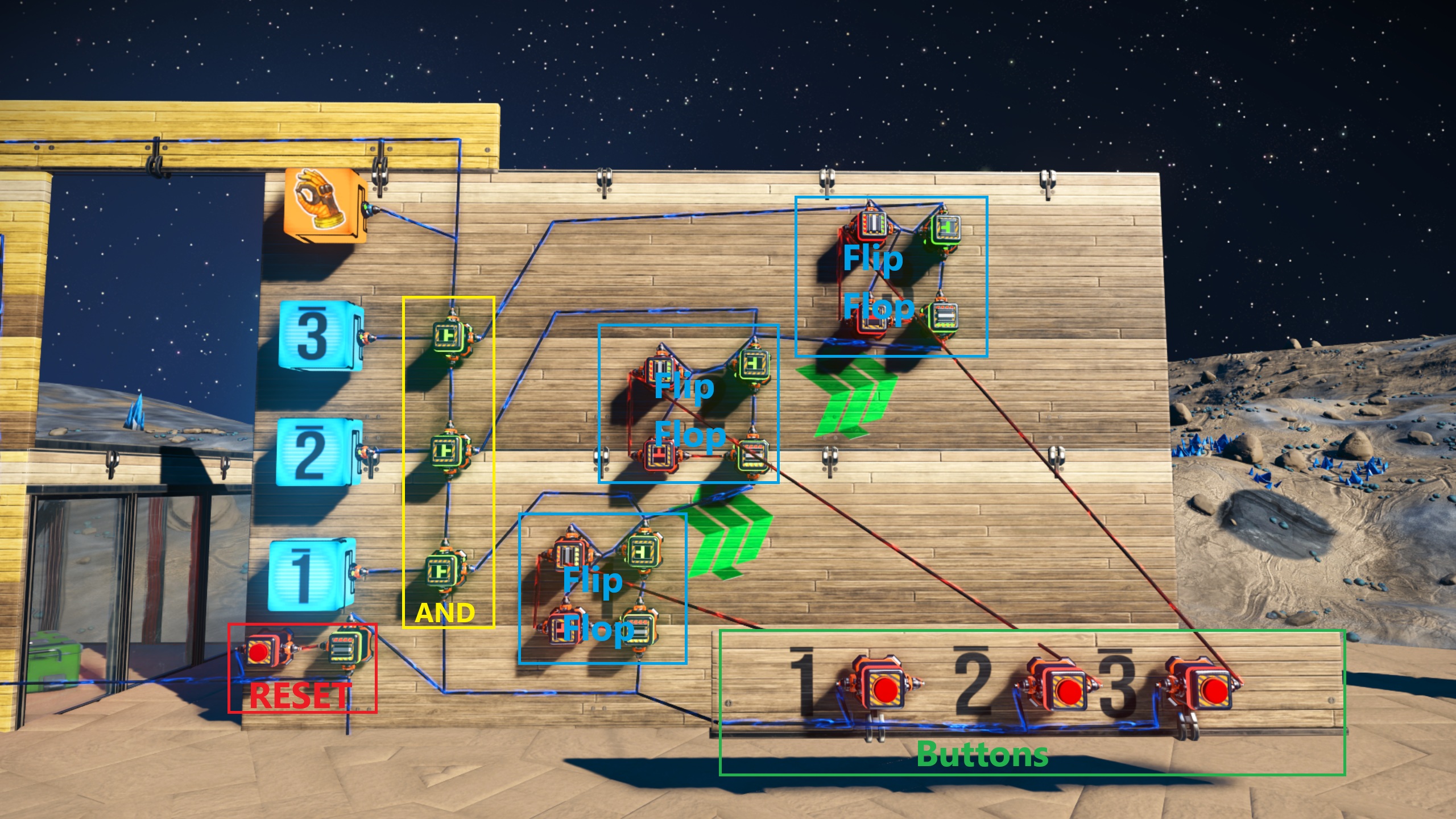
In the red box at bottom left, there is what I call a RESET circuit. It's just two part :
a button (left) and an inverter (right). It's connected to the main power (bottom) and on top, it deliver the current to the rest of the circuit. All the power delivered to the rest of the circuit passthrough it.
When you press the button, the power is down for a brief moment (one tick), and clear the full circuit. It's a RESET
OR

An OR gate purpose is simple: it outputs the flow of power (light on) if any of its inputs (wall switches here) are on.
It’s like a rule saying, "If either A or B or C is true (open), the output is true."
NOR
A NOR gate is a combination of an OR gate followed by a NOT gate. It outputs the opposite (inverted) result of an OR gate
Think of a system where a light turns ON only when neither of three switches is ON. If either switch is flipped, the light turns OFF.
The NOR gate is powerful due to its versatility and role in simplifying circuit designs!
AND
An AND gate is a basic logic gate that outputs 1 (HIGH) only when all of its inputs are 1 (HIGH). If any input is 0 (LOW), the output will be 0 (LOW).
Yes we started talking in Binary :)
On other terms, If all the switches are ON, then the light is ON. If one of them is OFF, the light turn OFF.
It's my personal fav :)
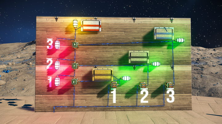
AND with 4 garage doors
AND gate with 3 switches to open or close garage doors.
Each switch got a lamp to test the circuit and follow the flow of energy. Green for the wall switches, Pink for the state of the AND gate, and Yellow for the Result (also call "Q")
+ If only one door is open (1,2 or 3), then the fourth door is open (the white door at top).
+ If 1 and 2 and 3 are closed, then the fourth door will close.
NAND
A NAND gate is the inverse of an AND gate. It combines an AND gate with a NOT gate to invert the output
Imagine a system where a warning alarm should only remain silent if both conditions are met (e.g., door is closed and no proximity sensor activated). If either condition deviates, the alarm will sound.
XOR
An XOR gate (exclusive OR gate) is a logic gate that outputs HIGH (1) if exactly one of its inputs is HIGH (1). It differs from a standard OR gate because it excludes the case where both inputs are HIGH (1)
Imagine a light controlled by two switches, but the light turns on only when one switch is flipped, not both. If both switches are off or on, the light stays off
XOR to open a loot door

We use a XOR to open an electric door when you win one of two game, but not both
Find more about this XOR example
XNOR
An XNOR gate (exclusive NOR gate) is the complement of an XOR gate. It outputs HIGH (1) if the inputs are the same (both 0 or both 1). If the inputs are different, the output is LOW (0).
Imagine a digital lock that only opens when two inputs (like PINs) match. If the inputs are the same, the lock opens. If they differ, it stays locked.
IMPLY
An IMPLY gate (or implication gate) is a less common but interesting logic gate that models logical implication. It outputs LOW (0) only when the first input (called the antecedent) is TRUE (1) and the second input (called the consequent) is FALSE (0). In all other cases, the output is HIGH (1).
Consider a rule like: If it rains (A), then I will carry an umbrella (B).
If A, then B (or 𝐴 → 𝐵).
Yeah, I know. It's not very useful in No Man's Sky :)
NIMPLY
The NIMPLY gate (also known as the NOT implication gate or negated implication) is the negated form of the IMPLY gate.
If it does not rain (A), then I do not carry an umbrella (B)
Even less useful in NMS, but who knows ? ^^
MUX & DEMUX

MUX and DEMUX are in another post
main source : No Man's Sky wiki
Visit the No Man's Sky School of Technology (in Euclid)


